 English
 Türkçe
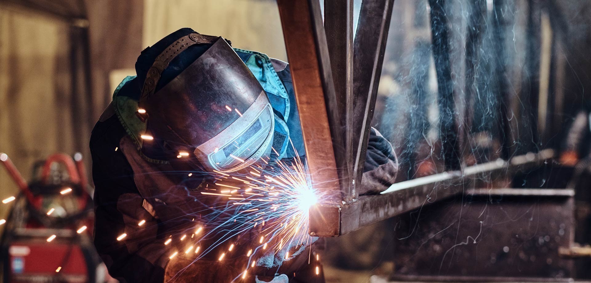
Welded Manufacturing Solutions
Desman provides high-quality industrial and technical solutions in the field of welded manufacturing. Our company offers services fully compliant with industry requirements, utilizing certified welders and advanced welding equipment. Including methods such as TIG, MIG, MAG, and laser welding, all stages—from welding engineering to mold design, preparation processes to post-weld heat treatment and cleaning—are systematically managed. Processes are conducted within the framework of international standards such as TS EN 15085-2 and TS EN ISO 3834-2, adhering to tight tolerance ranges and traceability requirements.
Desman’s comprehensive service portfolio includes the following areas:
- Welded manufacturing services (TIG, MIG, MAG)
- Industrial welding engineering
- Weld mold design and production
- Red-line drawing calculations
- Fixture design and production
- Pre-weld surface preparation
- Post-weld correction and cleaning
Thanks to its high engineering expertise, process-oriented quality control systems, and industry experience, Desman delivers reliable and precise solutions for specific welded manufacturing needs in sectors such as rail systems, defense, aviation, and energy.
Material Groups and Processable Thickness Ranges
Below is a summary of the material types and weldable thicknesses within Desman’s scope of work:
|
Material Types |
Thickness (mm) |
|---|---|
|
Carbon Steel |
1 – 30 |
|
Stainless Steel |
1 – 5 |
|
Aluminum |
1 – 5 |
Welding Equipment Used
The following welding machines are used in the production line, where technical proficiency is maintained at a high level:
|
Brand |
Model |
Type |
|---|---|---|
|
Fronius |
Magic Wave 230A |
Water-Cooled TIG Machine |
|
Fronius |
Magic Wave 300A |
Water-Cooled TIG Machine |
|
Fronius |
Transteel 400A |
Water-Cooled MIG Machine |
|
Lincoln |
320A |
Water-Cooled MIG Machine |
All projects are managed by certified welders in accordance with technical drawings and documentation, following WPQR and WPS procedures. Quality control practices are meticulously applied at every stage of the welding process, ensuring structural reliability.
Thanks to Desman’s capabilities, welding operations on various materials from 1 mm to 30 mm are performed seamlessly and in compliance with standards, particularly in applications requiring precise tolerances and adherence to standards.
What is Welded Manufacturing?
"Welded manufacturing is an advanced production technique in which metal materials are joined at the atomic level."
In this process, the parts to be joined are melted with controlled heat and brought together. During cooling, a homogeneous metallurgical structure forms in the weld zone, resulting in mechanical properties equivalent to the base material.
In this method, metallic bonds are re-established, and diffusion processes are optimized. It is particularly preferred for structural applications requiring high strength. Protective gas atmospheres and special flux materials are used to prevent oxidation and contamination.
In industry, welded manufacturing includes the joining of steel structures, stainless systems, aluminum alloys, and specialty metals. Microstructural control and heat treatment applications can enhance material properties.
Table of Contents
- Welded Manufacturing Solutions
- Material Groups and Processable Thickness Ranges
- What is Welded Manufacturing?
- Welding Methods
- International Welding Standards
- Weld Imperfection Control Processes
- Weld Imperfections
- Weld Imperfection Drawings
- Welded Manufacturing NACE Code
- Weld Imperfection Symbols and Their Meanings
- What is Weld Imperfection?
Welding Methods
Gas Metal Arc Welding (MIG/MAG)
Gas Metal Arc Welding (MIG/MAG) is a semi-automatic welding method performed under a protective gas atmosphere. In MIG (Metal Inert Gas) welding, inert gases such as argon or helium are used. In MAG (Metal Active Gas) welding, carbon dioxide or argon-carbon dioxide mixtures are utilized. This method is effectively applied to metals with thicknesses ranging from 0.8 mm to 25 mm.
MIG/MAG welding stands out for its high penetration power. Slag formation is minimal, and continuous welding is possible. Automatic wire feeding reduces operator intervention. Consistent weld quality is achieved in production. In serial production, a welding speed of 2-3 meters per minute can be achieved.
"Digital parameter control allows precise adjustment of weld depth and seam geometry."
TIG Welding
TIG (Tungsten Inert Gas) welding is a precise method using a tungsten electrode and performed in an argon gas atmosphere. It is preferred for thin, high-quality applications ranging from 0.5 mm to 10 mm. TIG welding keeps heat input to a minimum, resulting in high metallurgical quality.
"In TIG welding, the electrode does not wear out, and the weld seam is clean."
TIG welding is used for joining stainless steel pipes, aluminum components, and titanium parts. Process control is achieved through amperage settings, gas flow, and electrode angle. This method is frequently used in aviation, nuclear, chemical, and medical device manufacturing. X-ray quality seams can be achieved, meeting standards such as AWS D17.1.
Other Welding Methods
Shielded Metal Arc Welding (SMAW), Flux-Cored Arc Welding (FCAW), and Submerged Arc Welding (SAW) are other methods that can be used. Laser welding enables precise joints with low heat impact. Friction welding is particularly suitable for joining dissimilar metals.
Plasma arc welding provides good results in thick sections with high temperature and concentrated heat. The choice of method depends on material properties, part geometry, and performance requirements.
International Welding Standards
The ISO 3834 series specifies the requirements for a welded manufacturing quality management system, covering personnel competency, procedures, equipment calibration, and record-keeping processes. ISO 3834-2 requires full quality assurance, while ISO 3834-3 specifies standard quality requirements.
EN 1090 is mandatory for steel and aluminum structures to obtain CE marking. The standard regulates welding procedures (WPS), tests (WPQT), and welder certification. ASME Section IX applies to pressure vessels and piping systems. AWS codes are oriented toward American standards.
In the defense industry, AQAP-2110 is applied, while AS9100 is used in aviation. For rail systems, IRIS EN 15085 is prominent. Traceability, non-destructive testing, and metallurgical analysis are key components of these standards.
Weld Imperfection Control Processes
Weld imperfection control is conducted in three stages: pre-production, during production, and post-production. Before production, material certificates, procedure approvals, and equipment calibration are checked. Chemical composition and mechanical properties are analyzed.
During production, visual inspection, dimensional control, and parameter monitoring are ongoing. Penetration, seam width, and surface quality are constantly monitored. Real-time monitoring systems quickly detect any deviations.
"Post-production involves non-destructive testing methods, including radiography, ultrasonic, magnetic particle, and liquid penetrant tests."
Weld Imperfections
Imperfection Table
According to ISO 13920, weld imperfections are classified into four categories: A (precise), B (medium), C (rough), and D (very rough). Class A imperfections range from ±1-2 mm, while Class D can go up to ±10-15 mm. The class is determined based on the application area.
Angular imperfections typically range from ±1° to ±5°. Tighter imperfections are required for critical dimensions. Linearity imperfection can range between 1/1000 and 1/500 of the structure’s length. Seam height and width are also determined by imperfections.
"Post-weld heat treatments and stress relief ensure dimensional stability. Proper fixture design and welding sequence planning minimize deformation."
Weld Imperfection Drawings
The ISO 2553 standard is used for preparing weld imperfection drawings. Drawings clearly indicate the weld type, seam size, and control level. Technical drawings are categorized as manufacturing, assembly, and detail drawings.
Weld symbols consist of an arrow, reference line, and additional components. Seam type, size, length, and surface treatments are indicated through symbols. Automated symbol generation and 3D weld visualization are possible in CAD systems.
"Quality documentation includes WPS, WPQR, and WQR documents, which play a key role in manufacturing control and quality assurance."
Welded Manufacturing NACE Code
According to the NACE Rev.2 system, welded manufacturing activities are defined under code 25.61, which covers metal processing and welding services. Companies use this code for statistical classification and official transactions.
"The NACE code is used in industrial classification and official reporting."
Weld Imperfection Symbols and Their Meanings
Weld imperfection symbols are determined according to ISO 2553 and AWS A2.4 standards. Basic symbols include fillet weld (⩘), butt weld (I), V and U groove welds (V, U), and plug weld (○). Symbols include information on seam type, size, and placement.
Additional symbols indicate weld contour (flat, convex, concave), surface treatment (grinding G, machining M), and field welding requirements (flag ♛). A circle is used for continuous welds, and staggered symbols for intermittent welds.
Complex connections are represented by a combination of multiple symbols. Non-destructive testing requirements are also marked with special symbols. Standard symbols ensure accuracy and quality consistency in manufacturing.
What is Weld Imperfection?
Weld imperfection refers to the amount of energy applied per unit length, typically measured in kJ/mm or kJ/cm. It is calculated using the formula: HI = (V × I × 60) / (1000 × S). Heat input directly affects microstructure formation and mechanical properties.
"Excessive heat can cause grain growth and loss of toughness, while insufficient heat input may prevent complete fusion."
The appropriate heat range is determined based on material type, thickness, and joint geometry. Carbon equivalent calculations are used to assess weldability in steels.
The properties of the heat-affected zone (HAZ) depend on maximum temperature, cooling rate, and chemical composition. Controlled cooling, PWHT (post-weld heat treatment), and interpass temperature control can improve material properties. Heat distribution can be predicted through thermal analysis and numerical modeling.
"In modern welding technologies, adaptive control systems monitor and automatically adjust weld imperfection in real-time."
The welded manufacturing sector, with continuously evolving technology and automation, provides solutions that meet the demands of modern industry. With quality assurance and advancing engineering practices, welded manufacturing will continue to deliver safe and efficient solutions in the future.